
Home
Mission Statement
Editorial Policy
Submission Information
Volume One
Casual Papers
Fort Guijarros
Volume Two
To view pdf files you will
need Adobe Reader.
![]()
Fort Guijarros Structural Analysis: Facts and Deductions
C. Frederick Buchanan
It is the primary purpose of this report to present structural facts, findings, and deductions from the 1981 through 1995 archaeological excavations at the site of the old Spanish Fort Guijarros at the base of Ballast Point, Point Loma, San Diego. The fort was authorized by the King of Spain and in 1796 was constructed on Punta de los Guijarros, literally Cobblestone Point, in San Diego. Spanish planners selected this site at the mouth of San Diego Bay for a cannon battery which could effectively defend the Royal Presidio de San Diego from enemy invasion. The fort was originally dedicated and named San Joaquin. No Spanish or Mexican maps, drawings, or records have yet been found to describe the appearance of Fort Guijarros; however, an 1851 United States Coast Survey Map of Ballast Point provides strong evidence of a three-sided chevron-shaped battery (Figure 9.1).
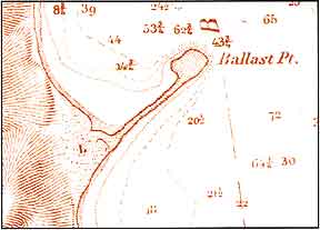 |
Figure 9.1 United States Coast Survey Map showing shape of (ruined) Spanish Battery, 1851. By A. M. Harrison. |
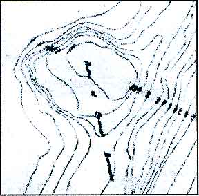
Also, an 1867 United States Army Corps of Engineers’ Map of Ballast
Point suggests location and orientation of the battery (Figure 9.2).
Figure 9.2 Topographic contours
of ruins of Spanish Battery. 1867 map by Thomas H. Hanbury. |
 |
In the absence of Spanish plans or engineering designs for Fort Guijarros,
there is indirect evidence of the fort’s general shape and design
in existing plans and sketches of Spanish cannon batteries in Nootka,
British Columbia and San Francisco, California. Other indirect evidence
of design can be drawn from the 1772 writings of de Lucuze. Based on historic
and archaeological evidence, artist Jay Wegter created a painting of what
Fort Guijarros might have looked like in 1800 (Figure 9.3).
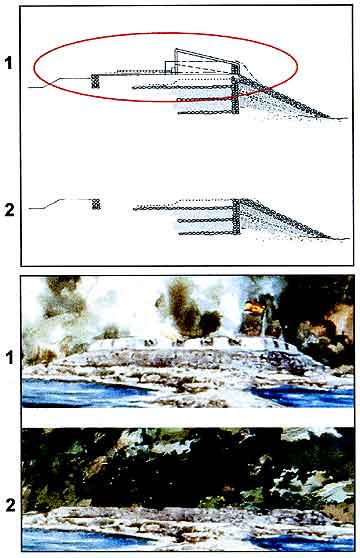
Figure 9.3 Top: 1 and 2 show fort cross-section before and after removal of the parapet walls. Bottom: These illustrations show a portion of Jay Wegter’s watercolor Battle of San Diego Bay depicting (1) a hypothetical view of Fort Guijarros and (2) the fort with the removal of the upper walls.
At the site of Fort Guijarros, the uppermost portion of the remains
is likely the eroded parapet of the structure. It is possible that whalers
using the site in later years may have altered this area, but it is
doubtful they would have reduced this elevation significantly. Therefore,
allowing for a small error in the surveyors' established zero elevation
of MLLW, 17 feet is thought to be the elevation of the eroded parapet
fill after salvage operations removed the tile and stucco protective
cover (see figure 9.3).
This demolition was probably a combination of Juan Machado removing
usable tiles and wood under a Mexican salvage permit in 1840, later
whalers clearing the site of debris, and the 1853 contractors who salvaged
tile for re-use in the U.S. Lighthouse atop Point Loma. Furthermore,
the cobblestones contained in the Fort Guijarros revetment to fend off
high tide and surf erosion would have made a handy source of ballast
for the many ships doing business at the adjacent Port of San Diego.
The 1896 U.S. Army 1-Foot Contour May by Lt. Deakyne is a plan for construction
of what was then a state-of-the-art coastal artillery battery, Battery
Wilkenson. This map, when compared with the 1867 map, shows the work
begun by the Army in 1873-74 in preparation for construction of a Coastal
Cannon Battery. In 1894, Congress stopped their project due to advances
in European artillery. This 1896 plan reveals the fact that considerable
work was done in 1873 to construct the earth pad for the Cannon Battery,
leveling higher ground for sight and firing clearances. The old Fort
Guijarros site with its uppermost ruins at 17 feet above MLLW was lowered
to about 12 feet above MLLW. Therefore, it is concluded that not only
has old Fort Guijarros lost its 7-to-8-foot parapet walls to salvagers
and site-clearers, but also several feet of the overall fort construction
due to Army Corps activity.
In the 1981 archaeological excavations, it was determined that the 24.36-to-27.6-inch-thick
cobblestone muro (core wall of the fort) and the stone, earth, and sand
revetment structures seaward of the core wall were all founded on the
beach (Figures 9.4 and 9.5). The bottom of the wall was found at 0.68
feet above MLLW, while the top of the remaining wall was found at 11.46
feet above MLLW (1981 determination).
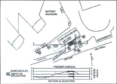
Figure 9.4 Layout of Fort Guijarros excavation Fields I, II, III, IV, V, VI, VII, and VIII in the vicinity of Building 539, Rosecrans Street and Battery Wilkeson. Note cross-section A-A at bottom, which shows the distinction between the present surface parking lot and the historical surface of the ruins of the fort in 1867.
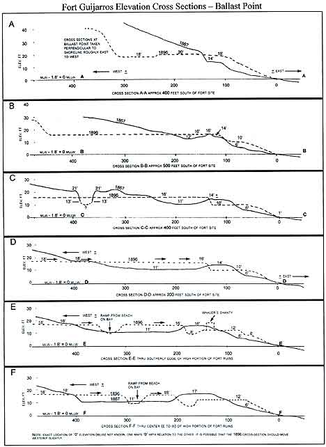
Figure 9.5 Cross-sectional views A-A, B-B, C-C, D-D, E-E, and F-F showing points along the beach at Ballast Point in relation to Fort Guijarros based on Thomas H. Hanbury’s Army Map dated 1867 and Lt. Deakyne Map dated 1896.
Some elevation could also have been lost during the Navy’s paving
work after the 1981 dig. The elevation of the top of the wall is reportedly
9.89 feet above MLLW. What remains of old Fort Guijarros is therefore
the bottom 10 feet of an earth, sand, and cobble substructure which
once stood at an elevation of some 21 feet above MLLW at the uppermost
height of its 8-foot earth, adobe, tile, and stucco parapet.
On top of the eroded original revetment layers lay the ruined remains
of the upper 10 or 11 feet of Fort Guijarros, where they lay after being
demolished and pushed or eroded over the seaward edge of the fort. Excavation
and research to date allow reconstruction of a probable cross-section
of the fort.
It is clear from the 1987 examination of exposed features that the parapet
could only have been supported by the core wall and the esplanade substructure
of cobblestone mats, sand layers, and compacted earth fill. The revetment
substructure seaward of the core wall does not appear to have any footing
capability for superstructure such as a heavy fort parapet.
Therefore, it is believed that the parapet was constructed from the
sea edge of the core wall back onto the esplanade fill (See
figure 9.3). Excavation of a fort cross-section (Field VIII) in
1993 provided evidence that the parapet and esplanade structure was
7 varas thick with a regulation esplanade depth able to handle cannons.
(A vara is an old Spanish dimensional measurement that generally falls
between a meter and a yard long.)
Specifically, the evidence is the fact that the horizontal cobblestone-and-sand-layered
substructure was found to extend from the fort core wall back not only
7 varas supporting the parapet but on back to form the substructure
for the esplanade. In front of the core wall the revetment layers buttressed
the mud-mortared cobblestone core wall at one time to near the esplanade
elevation. Figures 9.6 and 9.7 depict an actual cross-section of the
fort ruins in 1981.
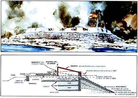
Figure 9.6 Top: Portion of Watercolor, Battle of San Diego Bay by Jay Wegter. Bottom: Fort Guijarros cross-section with identification of structural components: Parapeto, Merlons and Embrasures (Cannon Ports), Revestimento or Glacis, Banqueta, Cannon Platform, Sleepers, Terraplen, Plaza, Cobble Wall, and Magistral Line or Cordon.
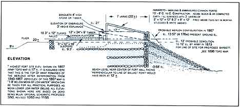
Figure 9.7 Fort Guijarros cross-section with identification of elevations and dimensions of proposed fort components.
Archaeology
Since 1981, the Fort Guijarros archaeological site was examined each
year at selected locations by teams from the Fort Guijarros Museum Foundation.
Eight test areas designated Field I through Field VIII were completed
in this effort (See figure
9.4). Each field was subdivided into grids of 3.28 to 6.56 feet
and hand-excavated in natural layers from surface to sterile; each grid
and layer was coded in order to document location of structure and artifacts
(Figure 9.8).
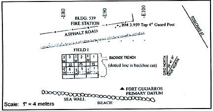
Figure 9.8 Map of Field I excavation units in 1981 south of Building 539, north of the sea wall.
Field I.
Spanish architecture of the fort was uncovered in a 16.4-by-29.53-foot
excavation (See figure 9.8) revealing a design using various sizes of
cobblestones, sand, earth, mortar, and both fired and unfired adobe.
These materials were substitutions for the quarry stone, or coquina,
traditionally used by the Spanish (Figures 9.8, 9.9 and 9.10).
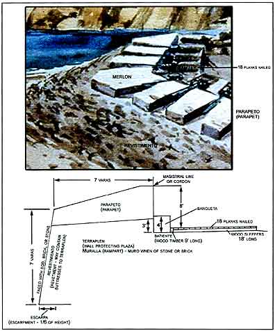
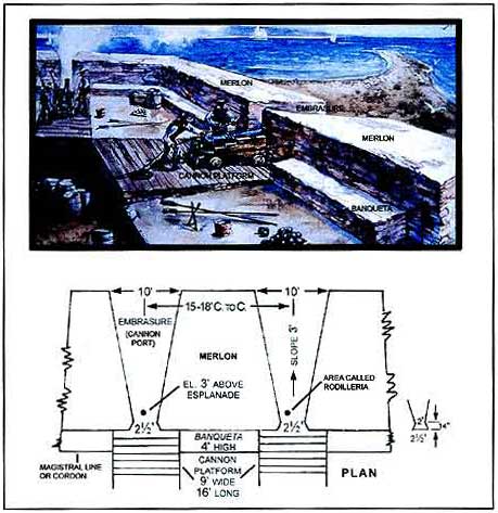
Figure 9.10 Illustration of fort components.
Field II.
(See figure 9.4) Excavation
of a 9.84-by-9.84-foot area west of Field I provided information on
the placement of the fort’s contrafuera or core wall, constructed
of mortared cobblestones. This particular portion of the fort extends
in a north–south direction. The southern extremities of the wall
have been eroded and encumbered by recently placed rip-rap wall and
waste concrete. It had been hoped to find evidence of the southerly
facing fort wall, which probably lies beneath the rip-rap seawall. Spanish
tiles, adobe, and mortar from the fort’s superstructure were reported.
Field III.
(See figure 9.4) At the
east edge of Field I, Field III measured 16.4 by 29.53 feet, examining
an area of Spanish beach for evidence of the 18th-century occupation.
The old beach level yielded broken and water-worn Spanish tiles, rusted
metal, bronze spikes, and an ornate brass rosette object. No evidence
of occupation appears to have survived the seasonal storms that scoured
the beach. However, tiles on sterile beach provide evidence of the easterly
extension of Fort Guijarros.
Field IV.
A 9.84-by16.4-foot area was examined west of Building 539, at the south
edge of the earthen revetment at the 1898 United States Army Coast Artillery
Battery Wilkeson. This search for evidence of the 1872–1874 American
Army battery construction lead excavators to a depth of 6.56 feet, below
which Spanish trash and artifacts were found. This suggested a barracks
and kitchen in the fort plaza area with items dating from the late 1790s
to early 1800s.
Field V.
At the southeast edge of Battery Wilkeson’s revetment, north of
Building 539, excavation to a depth of 6.56 feet penetrated United States
Army fill but failed to detect Spanish architecture. Negative findings
provide strong evidence that Fort Guijarros’s architecture terminated
directly under Building 539.
Field VI. Excavation and shoring of a 9.89-by-13.12-foot area to 8.86
feet revealed Spanish architecture 100 feet north of Building 539. Although
not primary elements of the Spanish battery, the artifacts found suggest
the presence of the barracks and kitchen.
Field VII.
Further west of Building 539 and Field IV, along the south side of Battery
Wilkeson, Field VII measured 11.48 by 13.12 feet and was excavated and
shored as a single unit to a depth of 8.86 feet. Artifacts such as Spanish
floor and roof tile were recovered along with Spanish trash providing
substantiating evidence that the plaza or parade ground area of the
fort hosted workshop, kitchen, and residential activities.
Field VIII.
Located along the south side of Building 539, Field VIII measured
91.8 by 16.4 feet in size and exposed an excellent cross-section of
the fort wall and overlying whaling and U.S. Army deposits. The cobblestone
substructure of the fort’s esplanade or cannon operating area
was exposed. The parapet area supported the merlons and cannon embrasures.
The contrafuera or core wall of the fort traversed the width of the
excavation, and a cobblestone revetment buttressed the massive clay-mortared
contrafuera. Spanish tiles, mortar, stucco, whitewash, and adobe melt
from the fort’s parapet covered the easterly down-sloping cobblestone
revetment. Evidence suggests the merlons and parapet structure decomposed
or were leveled by activity after the Mexican soldiers departed in 1835.
Methodology
Studies concerning the remains of Fort Guijarros use a grid system created
for unit 5 in Field I, in which the square was subdivided into component
subgrids with the intention of mapping in detail on large graph paper
and analyzing each architectural piece in the field. As each layer of
tiles were drawn and removed, another drawing was done on the lower layers
until eventually all tiles were recorded and removed. A notebook of sketches
with coded architectural observations was also created, providing both
a graphic documentation and a field notebook that identified the tiles
by the grid system, a description of the object, a sketch of the object,
the code system, a list of notes and a photograph. Later on, the tiles
were photographed again in the laboratory or returned to the field.
The methodology addressed three questions:
1. What documentation do we have for the shipment of tiles, wood, nails,
cement, and other materials? What about the 40,000 tiles?
2. What documentation shows details of similar forts?
a. From Historia de las Fortelezas de Santa Marta y Estudio Asesor para
su Restauración by Juan Manuel Zapatero we learn that the parapet
or merlon would be 7 feet high inside and 5 feet high inside and 13.5
feet thick. The rodilleras (cannon openings) are 2.5 feet wide and 11
feet 8 inches on center with the bottom of the opening and 3 feet from
the esplandade (deck). Banquetas are 3 feet high between cannon openings
for observation over the wall.
b. From the same source, we see that in the Fuerte San Fernando, the merlon
appears to be 5 feet wide with cannon ports 5 varas or 15 feet C to C.
3. Was our surveyor correct?
a. In 1981, Butch Hancock, Land Surveyor used the term AMSL after the
elevations recorded. This means Above Mean Sea Level, but, most surveys,
including Army and the Coast and Geodetic Survey, were MLLW. The closest
United States Coast Geodetic Survey monument is the “Coast Guard
Monument,” which is recorded on MLLW, and is some 700 feet east
of the Fort Guijarros marker.
Fort Guijarros Field Procedures
Field procedures consisted of the following seven steps: (1) Uncover all
structures and clean them, starting with the wall; (2) Map and photograph;
(3) Identify structural elements (tiles, cobbles, adobes, strata, etc.)
with number system (catalog numbers) on the map; (4) For each piece, apply
the Buchanan Code, i.e., A2 (BKLO) “fired adobe tile, 20 x 30 x
5 cm, broken size identifiable, mortar both sides, mortar impressions
of mating cobbles, mortar impressions of mating tile;” (5) Start
identification and coding system from wall working down over rubble as
mapping is completed; (6) Draw and photograph significant structural pieces;
and (7) Record all pieces on same 10 x 10 to 1 inch sheets as used by
C. Fred Buchanan on previous excavations.
Theory and Guide for 1987 Dig Based on the Analysis of the
1981 Findings.
Codes A-D represent architectural strata in the collapsed portion of the
merlon. The rubble of Strata 8 is designated as follows: Code A, brick
rubble; Code B, cobbles, sea weed, and brick rubble; Code C, mostly sand
and small cobbles; Code D, different colored sand and small cobbles lying
directly on top of Strata B (which is believed to be the original architecture
of the wall). At the time this test procedure was designed (Figure 9.11)
it was assumed that the surface of the glacis had been covered with mortar
or plaster.
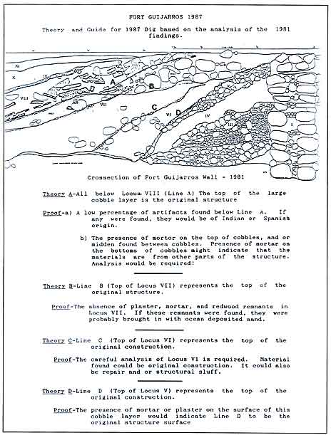
Figure 9.11 Theory and guide for 1987 dig.
Subsequent analysis in 1987 demonstrated that this was not the case. Hypothesis D proved to be correct, but without any mortar or plaster on the surface. This proof is based upon the lack of seaweed and rubble in Locus V. The studies presented here use a key of architectural codes (Figure 9.12).
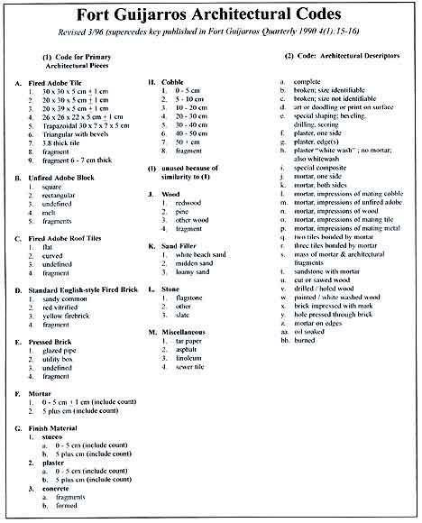
Figure 9.12 Fort Guijarros Architectural Codes that describe structural material found in the archaeological excavations.
This article concludes with a series of three appendices. Appendix A provides a summary of items analyzed from 1981 to 1995. It serves a starting point for additional structural studies that further address the hypotheses regarding the construction of Fort Guijarros. Appendices B and C are additional structural analyses.